Tag: piping design

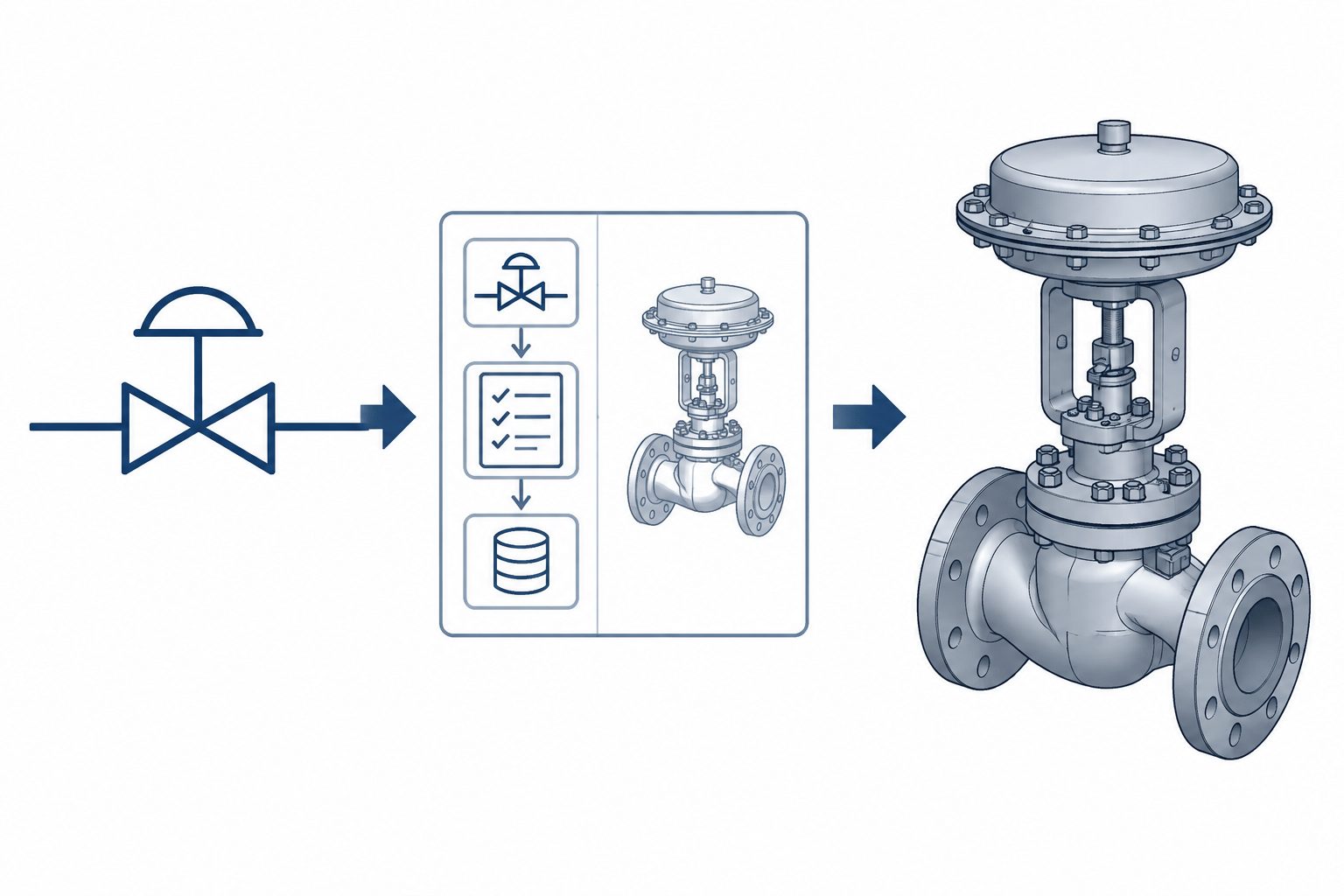
  • P&ID Symbols vs. 3D Piping Components: How to Translate Process Intent into CAD

    P&ID Symbols vs. 3D Piping Components: How to Translate Process Intent into CAD

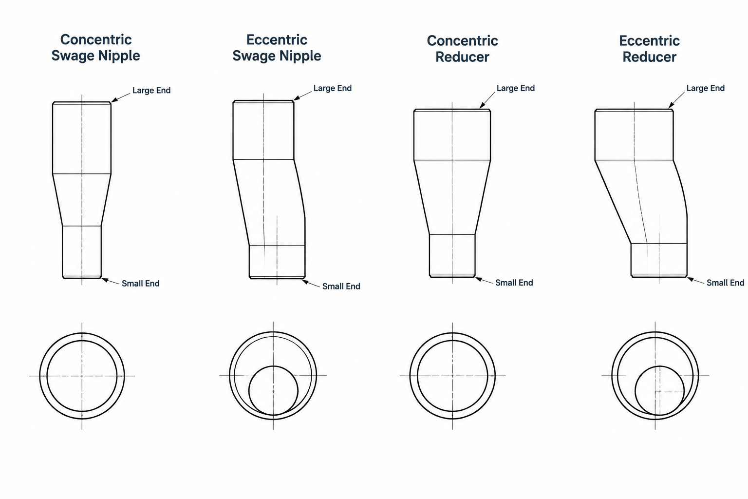
  • Swage Nipples vs. Pipe Reducers: Selection, Connections, and CAD Detailing

    Swage Nipples vs. Pipe Reducers: Selection, Connections, and CAD Detailing

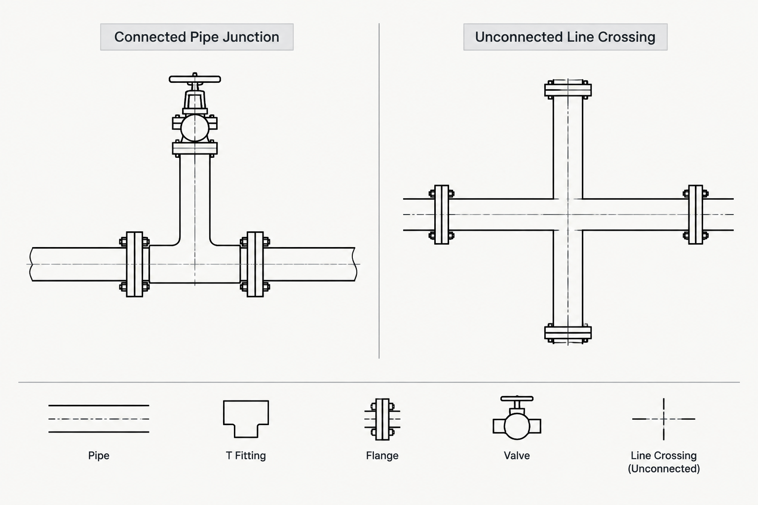
  • P&ID Line Crossings and Connections: How to Read and Draft Them Clearly

    P&ID Line Crossings and Connections: How to Read and Draft Them Clearly

  • Piping Weight Data in CAD: Dry, Operating, Test, and Insulated Loads

    Piping Weight Data in CAD: Dry, Operating, Test, and Insulated Loads

  • Piping Flange Types in CAD: How to Compare and Detail Common Connections

    Piping Flange Types in CAD: How to Compare and Detail Common Connections

  • Piping Document Handoffs: How P&IDs, Line Lists, Isometrics, and CAD Models Work Together

    Piping Document Handoffs: How P&IDs, Line Lists, Isometrics, and CAD Models Work Together

  • Piping Design Intent in CAD: How to Document Function Beyond Geometry

    Piping Design Intent in CAD: How to Document Function Beyond Geometry

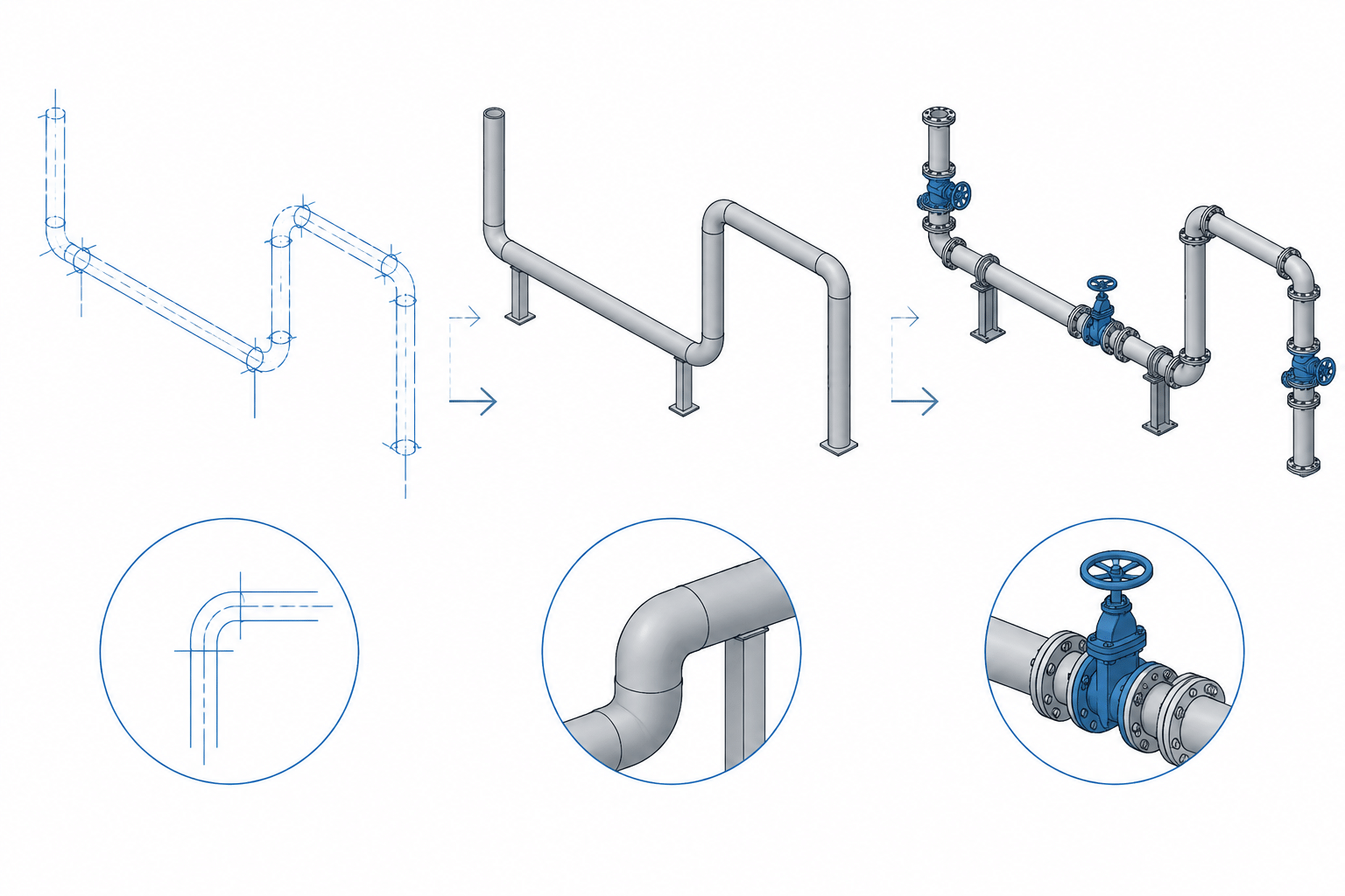
  • Piping CAD Model QA: How to Reconcile Geometry, Tags, and Bills of Material

    Piping CAD Model QA: How to Reconcile Geometry, Tags, and Bills of Material

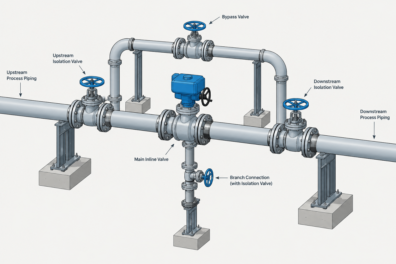
  • Piping Valve Access and Maintenance Clearances in CAD: A Practical Detailing Guide

    Piping Valve Access and Maintenance Clearances in CAD: A Practical Detailing Guide