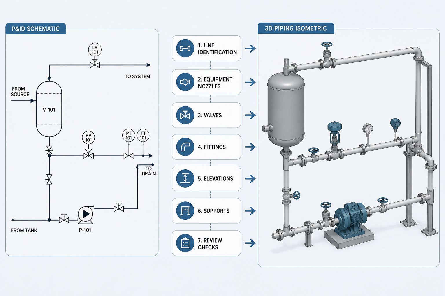
Converting a P&ID into a CAD piping isometric requires more than reproducing symbols in a different drawing format. The P&ID establishes process intent and line connectivity, while the isometric must communicate a verified physical arrangement that others can review, fabricate, install, and maintain.
This checklist-oriented guide helps drafters and engineers organize the handoff between process information, project piping data, equipment documents, and the CAD model. Use it to identify missing inputs early, distinguish verified geometry from schematic convention, and document questions instead of embedding assumptions in the drawing.
Turning a P&ID into a CAD piping isometric is not a matter of tracing every line from one drawing into another. A P&ID communicates process relationships and control intent, while an isometric communicates three-dimensional routing, component placement, connection details, and fabrication or installation information. The two drawings serve different purposes.

A reliable workflow therefore begins by separating what the process requires from what the physical model must show. This distinction helps prevent common errors such as inventing dimensions from a schematic, omitting valves, selecting the wrong fitting type, or treating a line number as a complete fabrication specification.
What a P&ID Provides—and What It Does Not
A P&ID commonly identifies process lines, equipment connections, valves, instruments, flow direction, reducers, drains, vents, and other functional items. It may also show line numbers and service information that point to a project piping specification.
However, a P&ID is generally not a scaled routing drawing. It should not be used by itself to determine:
- Exact pipe lengths or centerline coordinates
- Final elevations and slopes
- Clearances between adjacent systems
- Support locations and structural attachment details
- Fabrication spool boundaries
- The complete dimensional description of fittings, flanges, or valves
Use the P&ID as the process reference, then combine it with the equipment layout, piping arrangement, project specifications, design criteria, and approved component data. A separate reference on how to read pipe dimensions and schedule tables is useful when checking the physical pipe designation, but the table does not replace the project specification or model review.
Start with the Line List and Design Inputs
Before drawing, assemble the information associated with the line. The line number is an identifier, not a complete description. A useful working record should capture the pipe size designation, material or piping class, wall or schedule designation where applicable, insulation requirement, tracing requirement, design conditions, test requirements, and connection points.
Also identify the source and destination of the line. A line that appears simple on a P&ID may connect equipment nozzles at different elevations, pass through a structural zone, or include a required drain point that is not obvious in a preliminary layout.
At this stage, confirm the meaning of abbreviations and tags. For example, a valve symbol may identify function without fully defining the valve body, end connection, actuator, orientation, or access requirement. Those details normally come from the valve schedule, piping class, equipment documents, or the project model.
Build the Isometric from Connection Points
Begin with known physical constraints rather than the visual shape of the P&ID. Equipment nozzles, battery limits, tie-in points, and existing pipe connections provide the most reliable anchors for the route.
For each connection, record:
- Equipment or line reference
- Nozzle or tie-in identifier
- Nominal pipe size and connection type
- Orientation and available access space
- Required elevation or slope information
- Whether the connection is new, existing, or a field tie-in
Then develop the route using the project’s coordinate and elevation conventions. The isometric should make changes in direction, vertical offsets, branches, and connection points unambiguous. Do not infer a physical bend simply because the schematic line changes direction on the P&ID; schematic geometry is usually arranged for readability.
Translate Symbols into Physical Components
Every functional symbol on the P&ID should be accounted for in the isometric, but not every symbol has a one-to-one graphic equivalent. A control valve may require a valve body, actuator, flanges or weld ends, a bypass arrangement, vents or drains, and access space. An instrument connection may require a branch fitting, isolation valve, tubing connection, or a separate detail.
Create a component cross-check as you model. Useful fields include the tag, component type, size, end connection, rating or class designation when specified by the project, and the source document used for verification.
| Check item | Question for the CAD review |
|---|---|
| Valve | Is the correct valve tag shown, and is the operating side accessible? |
| Branch | Does the branch match the intended connection and orientation? |
| Reducer | Is the transition located and oriented correctly for the process and layout? |
| Flange | Does the flange type and facing information come from the approved project data? |
| Instrument | Is the instrument connection represented without confusing it with the main line? |
When selecting a component from a CAD library, verify more than its outline. Check the connection type, face-to-face dimension, orientation, nominal size, and project naming convention. PipeSTD’s fitting, flange, and CAD/DWG reference pages can support this comparison, while the project specification remains the controlling source for selection.
Use Fittings as Routing Decisions, Not Just Graphics
Elbows, tees, reducers, branch fittings, caps, and other components affect both the route and the amount of space required. In an isometric, the fitting representation should communicate the connection clearly and preserve the correct centerline relationship.
Common drafting mistakes include using a generic elbow block for a project-specific fitting, reversing a reducer, connecting a branch at the wrong angle, or placing a fitting where the actual component would interfere with a valve or support. A useful workflow is to confirm each fitting against three items: the line size, the connected component, and the piping class or material specification.
Do not fill in missing information by guessing from a familiar catalog arrangement. If the P&ID identifies a branch but the connection detail is unresolved, mark the item for engineering or piping-class review rather than silently choosing a component.
Show Supports, Access, and Installation Logic
An isometric is more useful when it reflects installation requirements, not only centerlines. Show support references or support locations according to the project’s drafting practice. Identify guides, anchors, shoes, spring supports, or other support concepts only when they are defined by the design or support documentation.
Review access around hand-operated valves, instruments, removable equipment, strainers, spectacle blinds, and flanged joints. A line can be geometrically connected while still being impractical to operate or maintain. Also check whether insulation, heat tracing, drain pockets, vents, and low-point collection requirements affect the route.
Support selection and flexibility are engineering activities. The isometric should document approved design intent; it should not be used to claim that a pipe arrangement is structurally adequate without the required analysis and review.
Dimension the Drawing from Verified Geometry
Once the route and components are established, add dimensions from the CAD model or verified layout—not by measuring the P&ID. Depending on the project, dimensions may include center-to-center distances, pipe cut lengths, elevations, coordinates, offsets, and spool break locations.
Keep dimensioning consistent with the drawing standard used by the project. Avoid overlapping dimensions, unclear witness lines, and dimensions that reference hidden or ambiguous points. For flanged connections, distinguish centerline dimensions from face-to-face or flange-face dimensions. The difference matters when the drawing will be used for fabrication, field fit-up, or material takeoff.
Perform a Structured Isometric Review
A final review should compare the isometric against the P&ID and the physical design documents in separate passes. This makes it easier to find both process omissions and layout errors.
- Process pass: Trace the line from source to destination and confirm flow direction, valves, instruments, branches, drains, vents, reducers, and tie-ins.
- Geometry pass: Check coordinates, elevations, slopes, bends, component orientation, and connection points against the model or layout.
- Component pass: Verify sizes, end connections, flange or fitting types, valve tags, and special items against approved data.
- Access pass: Check operation, maintenance, removal paths, insulation space, and visibility of critical tags.
- Documentation pass: Confirm line number, revision, material references, weld or joint identification, support references, and continuation symbols.
Record unresolved items clearly. A question mark or revision cloud is more useful than an unverified assumption hidden in the drawing.
Practical Takeaway
The best P&ID-to-isometric workflow treats the P&ID as a process map and the CAD model as a controlled physical translation. Start with verified connection points, build the route from project data, account for every functional component, and review process intent separately from geometry.
For reference work, keep component data close at hand: pipe dimension and schedule tables for terminology checks, fitting pages for connection geometry, flange references for interface details, and CAD/DWG resources for consistent representation. These references improve drafting efficiency, but they should support—not replace—the approved project documents and engineering review.
How to Use This Checklist in a Real CAD Workflow
Apply the checklist as a controlled review sequence rather than as a final visual inspection. First establish the documents that govern the line, then confirm the physical connection points, model the route, place the components, and review the finished isometric against both process and layout information. Keeping these activities separate makes it easier to determine whether an error came from process interpretation, component selection, or geometry.
Separate source information from drafting decisions
A useful mark-up or review log can classify each item as confirmed, pending, or requiring engineering disposition. Confirmed items may come from approved equipment documents, line data, piping classes, or the coordinated model. Pending items should remain visible until the responsible discipline resolves them. This approach is especially valuable when a P&ID identifies a function but does not define the physical connection, access arrangement, or installation detail.
Use drawing outputs as review evidence
The completed isometric should allow a reviewer to follow the line without repeatedly returning to the source documents. Clear tags, continuation references, component identities, connection points, support references, and verified dimensions all contribute to that traceability. If the drawing depends on a model view, equipment document, fitting reference, or project specification, record that relationship in the project’s normal document-control system.
Connect the workflow to reference information
When checking terminology or component representation, link the drafting process to the appropriate technical reference rather than relying on a generic CAD block. A pipe dimensions and schedules reference can help explain size and schedule terminology. fitting references, flange references, and CAD and DWG resources can support component comparison and drafting consistency. These resources are reference aids; the approved project data controls the actual selection.
Escalate uncertainty instead of hiding it
Unresolved routing, support, access, connection, or component questions should be recorded with an owner and disposition path. A visible review note, revision cloud, or controlled query is safer than selecting a familiar arrangement without evidence. This practice also gives later reviewers a clear explanation of why a drawing item remains open.
Recommended Handoff Package
- Marked-up P&ID showing the traced line and functional components
- Line data and applicable piping-class or material references
- Equipment, nozzle, tie-in, and existing-condition information
- Coordinated CAD model or layout used to establish routing and elevations
- Component cross-check covering valves, branches, reducers, flanges, instruments, and special items
- Review log identifying open questions, assumptions, and required approvals
This documentation makes the isometric easier to review and reduces the chance that a drafting convenience will be mistaken for approved engineering intent.
FAQ
Can a P&ID be used to create an isometric by itself?
No. A P&ID is a process and control reference, not normally a scaled routing model. Physical routing, dimensions, elevations, supports, access, and component details require the applicable project documents and verified layout information.
What should be checked before modeling the route?
Confirm the line identity, source and destination, equipment or tie-in references, connection information, applicable piping class, design inputs, and any existing-condition constraints. Unresolved inputs should be recorded before they become hidden CAD assumptions.
How should valves and instruments be represented?
Account for the functional item shown on the P&ID, then verify its physical representation from approved project data. Review the body, connection type, orientation, actuator or instrument arrangement, access needs, and any associated branches or accessories.
Why is schematic geometry not a reliable routing guide?
P&ID layouts are commonly arranged for readability and process tracing. A change in the direction of a schematic line does not necessarily represent a physical bend, offset, elevation change, or fitting in the installed system.
When should an isometric issue be escalated?
Escalate any issue involving an uncertain connection, missing component definition, conflicting source document, support or flexibility requirement, access problem, or unresolved physical constraint. The drawing should identify the question rather than silently resolve it by guesswork.
What is the difference between a component reference and the project specification?
A component reference can help explain terminology, geometry, and common drafting representation. The project specification, approved data, and engineering review determine what is acceptable for the actual line.