
Pipe and tube may look similar in a drawing, but they are not interchangeable product descriptions. Their sizing conventions, connection systems, database records, and bill-of-material requirements can differ significantly.
This guide helps CAD users, piping drafters, and document reviewers identify the correct product family and carry its terminology consistently from the source specification into the model and final drawing.
In everyday conversation, pipe and tube are often treated as interchangeable words. In engineering design and CAD documentation, that shortcut can create errors. The two products may differ in how they are sized, specified, manufactured, connected, and represented on drawings.
Understanding the distinction helps drafters interpret material specifications, select the correct database item, build clearer bills of material, and avoid mixing incompatible terminology. This guide explains the practical difference between pipe and tube without replacing the project specification, governing code, or approved manufacturer data.
What is the basic difference between pipe and tube?
Pipe is generally identified by a nominal size and a wall designation or schedule. Its main engineering purpose is to convey fluids, gases, or slurries. The nominal size is a reference designation rather than a direct measurement of the outside diameter. The actual inside diameter depends on the outside diameter and wall thickness associated with the selected product.
Tube is commonly identified by its actual outside diameter and wall thickness, although some tube products use other sizing systems. Tube is frequently selected for instrumentation, heat transfer, structural framing, mechanical assemblies, and applications where accurate outside dimensions are important.
These are useful general conventions, not universal rules. A project may use specialized pipe or tube products with different naming practices. Always confirm the applicable material specification and component catalog before modeling or detailing.
Pipe vs. tube: a practical comparison
| Topic | Pipe | Tube |
|---|---|---|
| Common size reference | Nominal size with an associated wall designation | Often actual outside diameter and wall thickness |
| Typical design purpose | Fluid conveyance and process piping | Instrumentation, heat transfer, structural, and mechanical uses |
| Common connection approach | Welded, flanged, threaded, grooved, or socket-connected systems | Compression fittings, tube fittings, brazed joints, welded joints, or specialized connectors |
| CAD library behavior | Often linked to nominal size, schedule, material, and piping class | Often linked to outside diameter, wall, material, and tube fitting family |
| Drawing risk | Confusing nominal size with measured diameter | Using pipe fittings or dimensions that do not match the tube system |
Why the distinction matters in a CAD model
1. The selected size may drive different geometry
A pipe component database may use nominal size as the primary lookup value, then apply the selected schedule or wall designation to determine the modeled bore and outside surface. A tube database may instead begin with the actual outside diameter and wall thickness.
If a drafter enters a nominal pipe size into a tube catalog, or treats a tube outside diameter as though it were a pipe nominal size, the resulting model can have the wrong bore, fitting size, or connection location. The error may not be obvious in a simplified plan view, but it can affect isometrics, spool drawings, clearances, and procurement information.

2. Fittings are not automatically interchangeable
Pipe elbows, tees, reducers, flanges, and valves are normally selected from a piping component system that matches the pipe size basis and connection type. Tube fittings may use compression nuts, ferrules, sockets, or other connection details that are not represented by a standard pipe fitting library.
Even when two products appear to have similar outside dimensions, their fitting interfaces may differ. Check the connection family, end preparation, material compatibility, and manufacturer or project requirements before substituting one for the other.
3. The bill of material may use different descriptions
Pipe descriptions commonly include nominal size, wall designation, material, end preparation, and length or form. Tube descriptions may emphasize outside diameter, wall thickness, material grade, temper, finish, or supplied length.
A CAD model should preserve the terminology used by the approved material list. Do not rewrite a tube description into a pipe-style description merely to make the schedule look consistent. Consistency is useful only when it does not hide the product identity.
How to identify pipe and tube in project documents
Use several clues rather than relying on one abbreviation. Review the following documents together:
- Piping material specification: Look for the product name, size basis, wall terminology, material, and permitted end connections.
- Line list or equipment connection schedule: Confirm whether the line belongs to a process piping system, utility system, instrument system, or equipment package.
- Component catalog: Check whether the item is indexed by nominal size or actual outside diameter.
- Fitting and valve descriptions: Compare the connection type on the straight product with the connection type on the fitting.
- Fabrication notes: Look for requirements related to bending, cutting, deburring, orbital welding, compression assembly, or cleanliness.
- Existing details: Use approved project drawings to confirm how the product is represented, tagged, and scheduled.
Abbreviations can vary between companies and software systems. A label that appears to mean tube may be a project-specific code, while a generic “pipe” label may be used by a CAD package for any cylindrical run. The governing description is the approved project data, not the software category alone.
CAD detailing workflow for pipe and tube
Step 1: Establish the product identity
Before drawing, record whether the item is pipe or tube, the applicable material description, and the connection family. If the source documents conflict, stop and resolve the discrepancy rather than guessing from appearance.
Step 2: Select the correct database family
Use a pipe component family for piping items and a tube family for tube items when both are available. Confirm that the family carries the correct size basis, wall property, material, and end condition.
Step 3: Model the connection, not just the centerline
A centerline can make pipe and tube look identical. Add the connection behavior needed for the drawing purpose: flange faces, threaded ends, tube fitting bodies, weld ends, ferrules, unions, or equipment interfaces. The amount of detail should match the drawing type, but the connection identity should remain unambiguous.
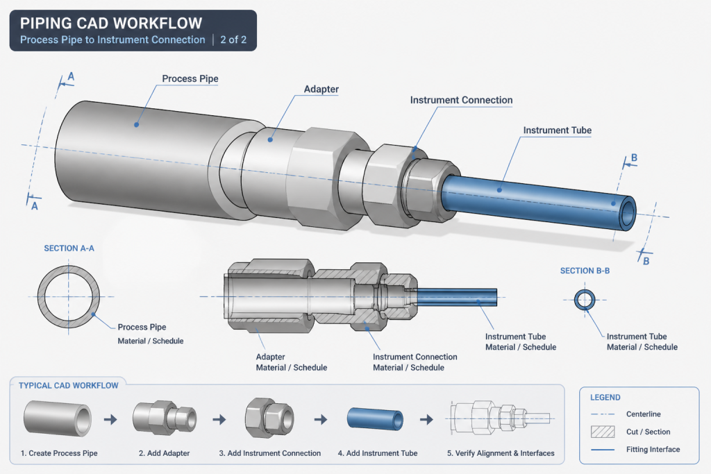
Step 4: Check interfaces at transitions
Where tube connects to pipe, equipment, or an instrument manifold, verify the transition component. It may require an adapter, fitting, flange, welded outlet, or supplied equipment connection. Do not assume that a direct connection is permitted simply because the graphics align.
Step 5: Verify schedules and tags
Review the model against the line list, material takeoff, and drawing annotations. Confirm that the size wording, wall description, material, and connection notes agree. A visually correct route with an incorrect product description is still a documentation error.
Common drafting mistakes
- Calling every small-diameter run tubing: Small size alone does not define tube. The material specification and connection system control the terminology.
- Using a pipe schedule for a tube item: This can create an invalid or misleading wall description.
- Scaling symbols to represent real dimensions: A schematic symbol is not a substitute for the approved component geometry.
- Using a pipe elbow for a tube bend: A bent tube and a manufactured pipe elbow may have different fabrication, centerline, and fitting requirements.
- Omitting adapters at interfaces: Different size systems and connection types often require a deliberate transition component.
- Changing terminology during revision: Renaming a product without updating the material schedule can create mismatches between drawings and procurement records.
Final review checklist
Before issuing a drawing or extracting a bill of material, ask:
- Is the item identified as pipe or tube in the source specification?
- Does the selected database use the correct size basis?
- Does the wall description match the product terminology?
- Do the fittings and connectors belong to the same connection system?
- Are pipe-to-tube transitions shown and described?
- Do tags, notes, schedules, and model properties agree?
- Have ambiguous or conflicting source documents been resolved?
The most reliable CAD workflow treats pipe and tube as related but distinct product systems. Once the size basis, connection method, and specification language are confirmed, the model becomes easier to check and the resulting drawings communicate more accurately with design, fabrication, procurement, and field teams.
How to use this guide in practice
The most important distinction is not the appearance of the cylindrical run. It is the relationship between the product identity, its sizing basis, its connection method, and the project documentation that controls it.
When reviewing a model, begin with the approved specification and material data rather than the software category or a visual assumption. Then check whether the selected component family, fittings, transitions, tags, and schedule descriptions all describe the same product system.
Where pipe and tube decisions affect project quality
- Model accuracy: The selected database family can determine the modeled outside surface, bore, fitting interface, and connection location.
- Fabrication clarity: Drawing details should distinguish manufactured fittings, tube bends, welded ends, compression connections, and other applicable interfaces.
- Procurement consistency: Product descriptions should retain the terminology and identifying properties used by the approved material list.
- Interface control: Pipe-to-tube connections should be reviewed as deliberate transitions rather than assumed direct connections.
Use the detailed comparison, document review guidance, workflow, and checklist below as a drafting aid. They support project review, but they do not replace the governing specification, applicable code, or approved manufacturer information.
Frequently asked questions
Is pipe the same as tube?
No. Pipe and tube are related cylindrical products, but they may use different sizing systems, specifications, connection methods, and CAD catalog families. Confirm the product identity in the approved project documentation.
Can a pipe fitting be used with tube?
Not automatically. The fitting must match the product’s size basis, connection family, end condition, material requirements, and project documentation. Similar-looking outside dimensions do not prove compatibility.
How should pipe and tube be selected in a CAD library?
Select the database family that matches the approved product description. Check the size basis, wall property, material, end condition, and connection behavior before using the item in a model.
How can a drafter tell whether a small run is pipe or tube?
Small size alone is not conclusive. Review the material specification, line or equipment documentation, component catalog, fitting descriptions, and fabrication notes together.
What should be checked when pipe connects to tube?
Verify the transition component and its connection interfaces. Depending on the approved design, the transition may involve an adapter, fitting, flange, welded outlet, or equipment connection.
Why does terminology matter in a bill of material?
Pipe and tube descriptions may emphasize different identifying properties. Preserving the approved terminology helps prevent mismatches between the CAD model, drawings, procurement records, and fabrication documentation.