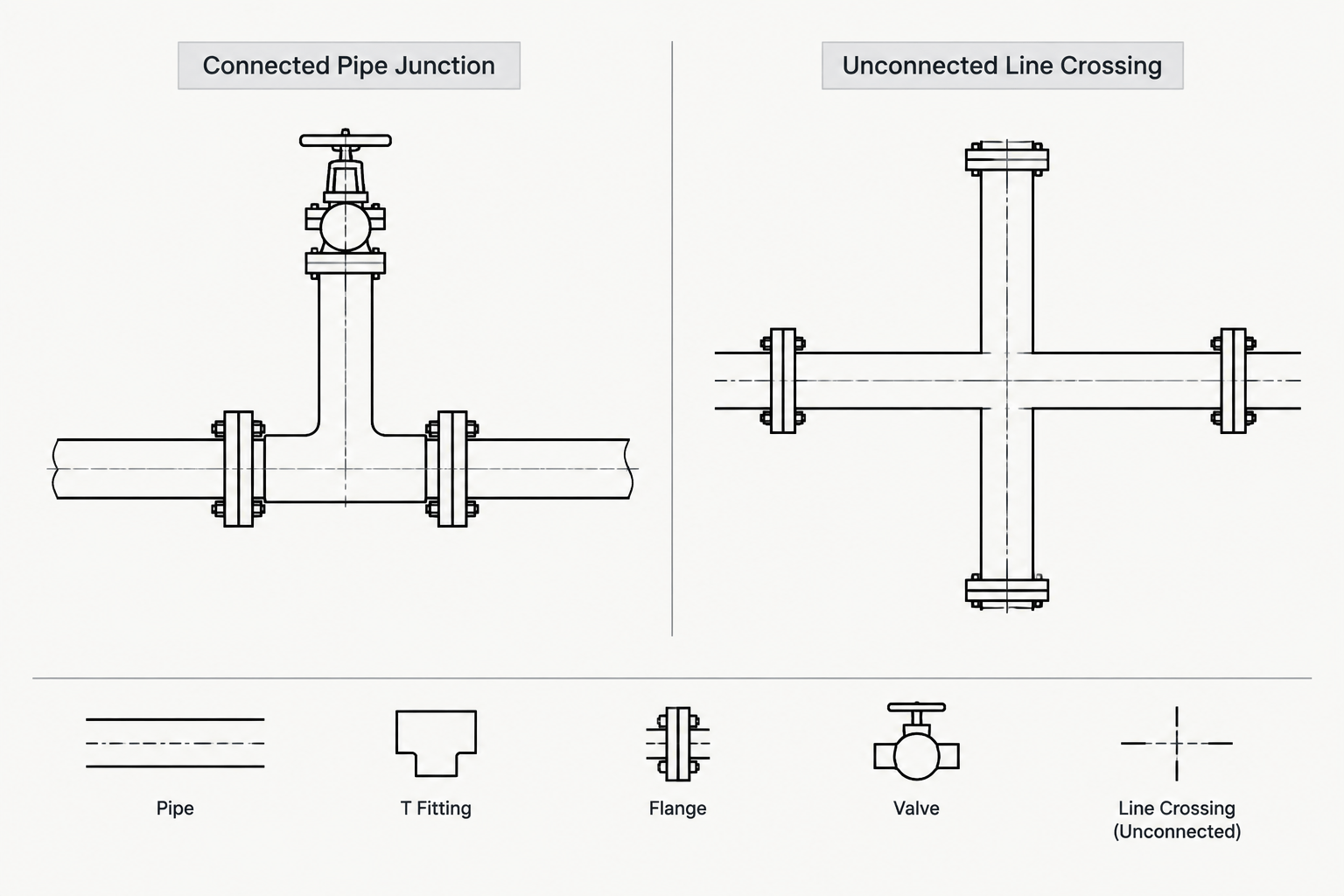
P&ID line crossings and connections can look deceptively similar, yet they communicate very different process relationships. Correct interpretation requires more than recognizing a familiar graphic. The reader must consider the project legend, line identity, service, endpoints, flow direction, and the functional logic shown across the document set.
This guide explains how to evaluate ambiguous intersections, draft them more clearly, and preserve their meaning in both conventional CAD drawings and data-driven P&ID systems. It also separates functional connectivity from physical piping layout so that diagram geometry is not mistaken for routing or elevation.
A process and instrumentation diagram may contain dozens of intersecting process lines, utility lines, instrument signals, and equipment connections. Some intersections represent connected branches. Others are only graphical crossings between unrelated systems. Confusing the two can create false connectivity, incorrect line lists, routing errors, or hazardous operating assumptions.
The challenge is not simply recognizing a dot or line break. P&ID conventions vary among owners, engineering contractors, industries, and drawing systems. A symbol that means “connected” in one document set may be handled differently in another. The reliable approach is to read each intersection within the drawing’s documented conventions and then confirm it against tags, line numbers, flow direction, and process intent.
Crossing Is Not the Same as Connection
When two lines meet on a P&ID, the geometry alone does not always define their relationship. The intersection generally represents one of two conditions:
- Connected junction: Fluid, pressure, or a signal can pass from one line into the other.
- Unconnected crossing: The lines overlap only because of the two-dimensional drawing layout.
A connected junction may represent a tee, branch outlet, manifold connection, instrument takeoff, or another functional connection. An unconnected crossing has no physical relationship unless some other note or reference establishes one.
This distinction is especially important when a process line crosses a utility line or when an instrument signal crosses several piping lines. Adding an unintended junction can change the apparent operating function of an entire system.
Common Graphical Treatments
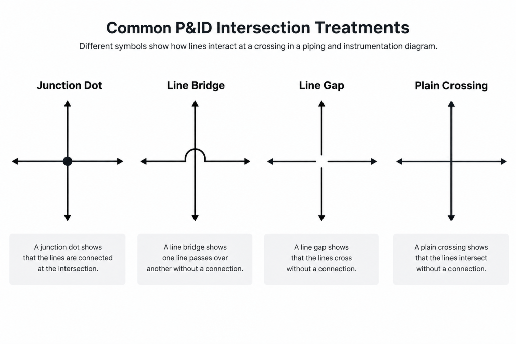
Organizations use several methods to distinguish crossings from connections. These methods should be treated as project conventions rather than universal rules.
Junction dot
A filled dot at an intersection commonly indicates that the lines are connected. This treatment can be effective when the dot remains clearly visible at the drawing’s issue scale. Very small dots, heavy lineweights, and low-quality document scans can make the meaning uncertain.
Line jump or bridge
One line may curve or “jump” over another to show that the lines do not connect. This is visually clear in many cases, but the jump should not resemble a piping loop, flexible connection, or other project symbol.
Line gap
A short break in one line may indicate an unconnected crossing. Gaps require careful drafting because a plotting problem, masking object, or accidental trim can look similar. The interrupted line should remain easy to follow through the crossing.
Plain intersection without a dot
Some drawing practices use a plain intersection for one condition and a dotted intersection for the other. This convention is vulnerable to misinterpretation if users assume rules learned from a different company or software environment. The project legend must resolve the meaning.
How to Determine What an Intersection Means
Do not decide from one graphic feature when additional information is available. Use a layered review:
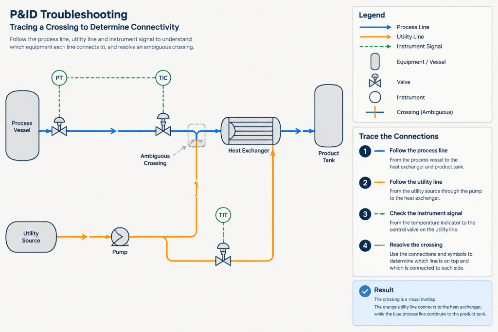
- Check the legend and drafting standard. Look for examples of connected branches, unconnected crossings, instrument signals, and continuation symbols.
- Trace both lines. Follow each line to its source and destination. Equipment nozzles, valves, instruments, and off-page connectors often reveal the intended function.
- Read the line identifiers. Different line numbers passing through the same intersection usually suggest a crossing, although specification breaks and branch numbering rules must also be considered.
- Review flow direction. Arrows can help expose a connection that would create an illogical flow path.
- Compare process and utility service. Ask whether the implied connection is functionally reasonable. Do not treat apparent reasonableness as final proof, however.
- Check related documents. The line list, equipment data, control narrative, system description, and other P&ID sheets may clarify the relationship.
- Raise a query if uncertainty remains. CAD geometry should not be used to invent missing process intent.
Related Conditions That Can Look Like Junctions
| Drawing condition | Possible confusion | Useful check |
|---|---|---|
| Instrument tap on a process line | May look like a full piping branch | Trace the signal or impulse-line convention and instrument tag |
| Off-page continuation | May look like a terminated line | Match the connector reference, service, and line identifier |
| Specification break | May be mistaken for a disconnected line | Review adjacent material or piping-class callouts |
| Reducer or size change | May appear to split the line | Check the fitting symbol and size notation |
| Control or electrical signal | May appear connected to crossed process piping | Use line type and endpoint symbols, not proximity alone |
| Multiple branches at one location | May conceal separate connections | Trace every branch independently and verify destination |
Drafting Practices That Reduce Ambiguity
Keep junctions away from crowded symbols
A connection placed directly beside a valve body, equipment outline, text label, or instrument bubble can be difficult to interpret. Where practical, provide enough open line length for the branch relationship to remain visible.
Avoid stacking unrelated intersections
Several lines crossing at one point can resemble a manifold even when none of them connect. Offset unrelated crossings or reroute signal lines to create distinct, readable intersections.
Use consistent junction graphics
Connected branches of the same type should receive the same treatment throughout the document set. Avoid manually drawing some junction markers while relying on software-generated behavior elsewhere unless the plotted results are identical.
Review at the issue scale
A junction may look obvious while zoomed in but disappear when printed or converted to a reduced-size document. Review dots, gaps, line jumps, and lineweights at the scale used for checking and issue.
Protect meaning during revisions
Moving a line can leave a junction dot behind, extend a gap into the wrong line, or create a new accidental intersection. After revisions, trace affected systems beyond the immediate markup area.
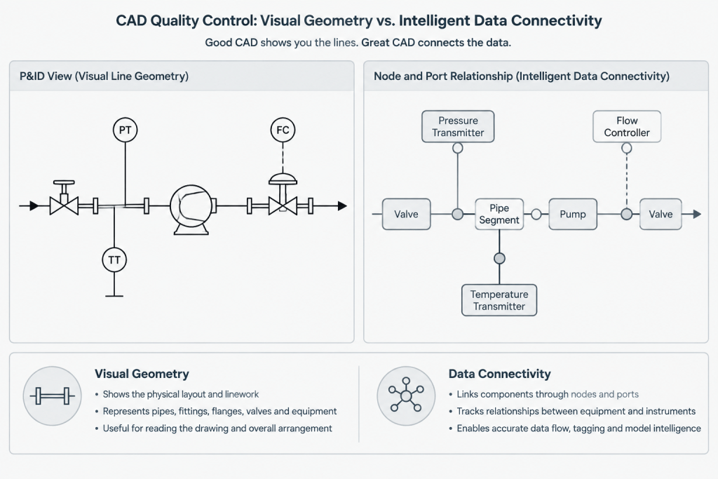
Using P&ID Connectivity in CAD and Data Workflows
Intelligent drafting systems may store relationships between lines, components, and equipment. A graphical crossing may therefore have a different data state from a true connected branch. The image can look correct while the underlying connectivity is wrong, or the database can show a connection that is not clear on the plotted drawing.
For data-driven P&IDs, check both presentation and connectivity. Confirm that a branch belongs to the intended pipeline, component ports connect to the correct line, off-page connectors pair correctly, and reports do not merge unrelated systems. Exploding symbols or replacing intelligent objects with ordinary lines can destroy these relationships even if the sheet still looks acceptable.
Handoff to Piping Layout and Isometrics
A P&ID defines functional relationships, but it usually does not establish the physical route or exact branch orientation. Once a connected branch is confirmed, the layout team must still determine where it can be installed, how it connects, what fitting or branch type applies, and whether access, drainage, stress, maintenance, and fabrication needs are satisfied.
Conversely, an unconnected graphical crossing on a P&ID does not tell the designer which physical pipe passes above the other. That spatial decision belongs in the piping model and layout drawings. The P&ID should not be interpreted as a scaled arrangement drawing.
Practical Review Checklist
- Verify the project convention for connected and unconnected intersections.
- Trace every questionable line to identifiable endpoints.
- Compare line numbers, services, sizes, and flow arrows.
- Distinguish process piping from instrument, electrical, and control signals.
- Check off-page connectors on both referenced sheets.
- Review junction visibility at the final issue scale.
- Confirm intelligent connectivity when the P&ID contains linked data.
- Do not infer physical routing or elevation from a graphical crossing.
- Document unresolved connectivity as a design query rather than guessing.
Clear P&ID line crossings and connections depend on more than neat graphics. They require consistent conventions, process-aware checking, and careful preservation of connectivity during revisions. When an intersection is ambiguous, the safest response is to trace, compare, and verify before the information reaches piping layout, procurement, fabrication, or operations.
Read the Intersection in Layers
A useful review method is to treat every questionable intersection as a combination of graphical, documentary, and data evidence. Agreement among these layers provides stronger confirmation than any isolated dot, gap, or line jump.
- Graphical evidence: Examine line types, junction markers, breaks, bridges, arrows, endpoint symbols, and nearby callouts at the intended issue scale.
- Documentary evidence: Compare the intersection with the legend, line list, equipment connections, off-page references, control information, and related drawing sheets.
- Data evidence: In an intelligent P&ID, inspect the stored pipeline and component relationships rather than assuming that visually touching objects are connected.
If these layers conflict, the conflict is a design-information issue rather than a drafting detail to resolve by assumption. A clear drawing can contain incorrect underlying connectivity, while a correct database relationship can remain poorly communicated on the plotted sheet.
Include Connectivity in Revision Checks
Connectivity review should extend beyond the location of a markup. Moving a line, replacing a symbol, changing an off-page connector, or adjusting a mask can alter how nearby intersections are read. In an intelligent drawing, edits may also detach objects or associate a branch with the wrong pipeline.
After a relevant revision, trace the affected path to recognizable endpoints and review the resulting output. Confirm that the visible convention remains clear, that identifiers and services remain coherent, and that generated information does not combine unrelated systems. This approach checks both drawing presentation and design meaning.
Separate Functional Intent from Physical Arrangement
A confirmed P&ID connection establishes a functional relationship, but it does not by itself define the installed branch orientation, elevation, fitting selection, or routing sequence. Those decisions must be developed and verified in the appropriate piping layout, model, and fabrication documents.
Likewise, an unconnected crossing communicates only that the lines are unrelated at that point on the diagram. It does not establish which pipe occupies the higher physical position. Keeping this boundary clear helps prevent schematic drafting from being treated as spatial design information.
Frequently Asked Questions
Does a junction dot always mean that P&ID lines are connected?
No universal interpretation should be assumed. A filled junction dot commonly indicates connectivity, but the project legend and documented drafting practice control the meaning for the drawing set.
Does an intersection without a dot always mean the lines are unconnected?
Not necessarily. Some organizations distinguish conditions with dots, gaps, or line jumps, while others apply different graphical rules. Trace the lines and check the project convention before deciding.
Can line identifiers alone prove whether an intersection is connected?
Line identifiers are important evidence, but they should be considered with branch-numbering practices, specification changes, services, endpoints, and process intent. They should not be used as the only test when other information conflicts.
What should a drafter do when the intended connectivity is unclear?
Do not add or remove a connection based on visual preference. Record the uncertainty, identify the conflicting evidence, and request clarification from the responsible design discipline or document owner.
Does a crossing show which physical pipe passes above the other?
No. A P&ID is a functional diagram rather than a scaled piping arrangement. Physical elevation and routing must be determined from the piping model and applicable layout documents.
Why must intelligent P&ID connectivity be checked separately?
The plotted graphic and the stored data relationship can disagree. Objects may appear connected while remaining unrelated in the database, or the database may contain a connection that is not visually clear. Both states require review.