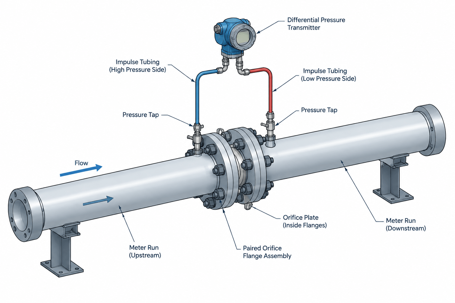
Orifice flanges and meter runs require more CAD coordination than a typical flanged piping joint. The model must preserve the relationship between the plate, pressure taps, flow direction, adjoining pipe, instrument connections, and maintenance access without replacing information controlled by process or instrumentation disciplines.
This guide explains how to represent that measurement assembly in piping CAD, coordinate its interfaces, and carry essential orientation information into isometrics and installation drawings. Approved piping specifications, instrument documents, meter data, and project procedures remain the governing sources for the final design.
Orifice flanges may resemble ordinary flanges in a piping model, but the surrounding assembly serves a measurement function. Its accuracy depends on more than connecting two pipe ends. The orifice plate, pressure taps, flow direction, upstream and downstream piping, instrument connections, and access requirements must work together as a coordinated meter installation.
For a CAD designer, the main challenge is deciding which information belongs in the piping model and which information must come from process, instrumentation, piping specifications, or a meter vendor. Treating the assembly as a generic flanged joint can conceal important orientation and dimensional requirements. Treating every detail as a piping decision can be equally risky.
What an orifice flange assembly does
An orifice plate is installed across the pipe bore to create a differential pressure as fluid passes through its opening. Pressure is sensed on each side of the plate, and the resulting differential is used as part of the flow measurement system.
A typical assembly may include:
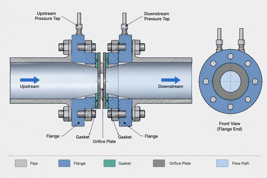
- A matched pair of orifice flanges
- An orifice plate located between the flanges
- Gaskets on the appropriate sides of the plate
- Pressure taps or tap connections
- Bolting and any required plate-handling hardware
- Impulse tubing or piping leading to a transmitter or manifold
- Supports for the meter run, impulse lines, and instruments
The exact arrangement is project-specific. The line class, measurement design, process service, applicable standards, and purchased equipment documentation should govern component selection and details.
Orifice flange pair versus complete meter run
An orifice flange pair is only the plate-holding and pressure-tapping portion of the installation. A meter run is the larger piping assembly associated with the measurement point. It can include upstream and downstream straight pipe, adjacent fittings, flow-conditioning equipment, the primary element, and instrument connections.
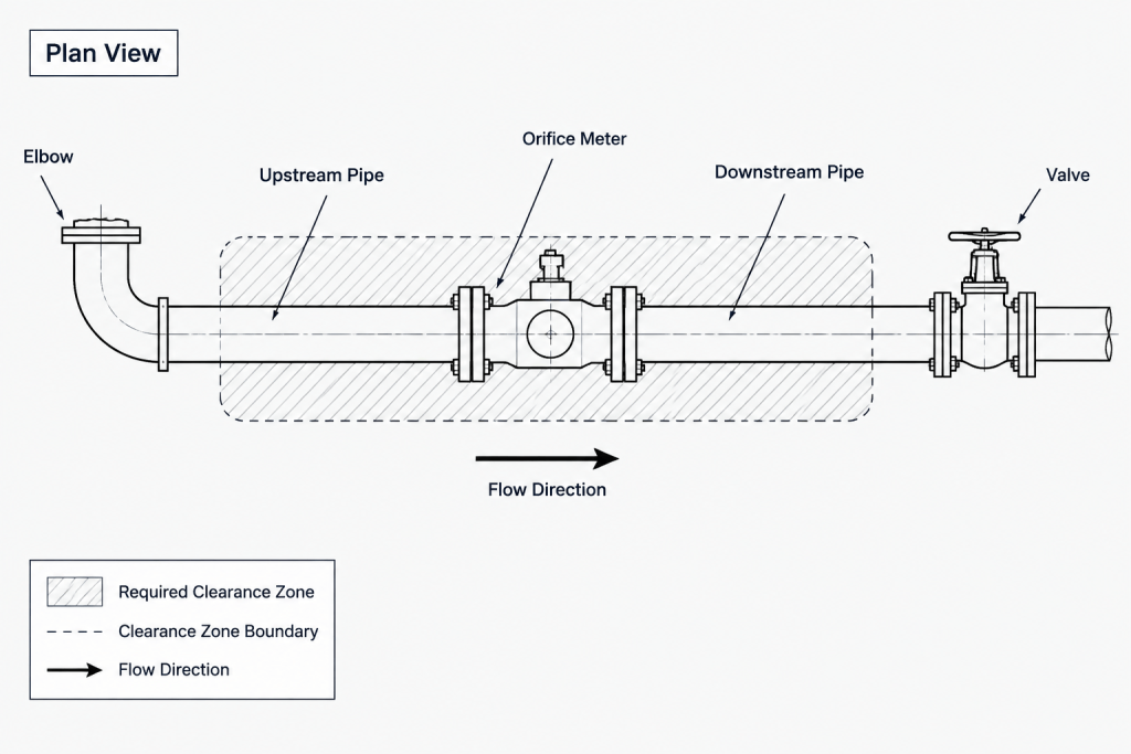
This distinction matters in CAD because the flange pair may be modeled correctly while the meter installation remains unsuitable. A nearby elbow, reducer, branch, valve, or partially open control element can affect the flow profile. Required straight-run arrangements should therefore be obtained from approved process or instrumentation documents rather than assumed from a generic drafting rule.
| Item | Primary concern | Typical information owner |
|---|---|---|
| Flange pair and bolting | Connection type, class, material, facing, and joint dimensions | Piping specification |
| Orifice plate | Bore, thickness, material, identification, and orientation | Process or instrumentation |
| Pressure taps | Tap type, location, orientation, and connection size | Instrumentation with piping coordination |
| Straight-run arrangement | Distance from flow disturbances and meter configuration | Process, instrumentation, or vendor |
| Transmitter and manifold | Location, access, mounting, and impulse-line routing | Instrumentation |
| Pipe supports | Structural stability, movement, and instrument protection | Piping and structural disciplines |
Model the assembly as functional components
A useful CAD representation should distinguish the flange pair, plate location, taps, and instrument interfaces. A single generic flange symbol may be adequate on a simplified diagram, but it is usually not enough for a fabrication model or detailed isometric.
At minimum, the detailed model should preserve:
- The correct face-to-face or assembly length from verified component data
- The centerline location of the orifice plate
- The intended upstream and downstream sides
- The pressure-tap locations and clocking
- The connection points for impulse lines
- Space needed to remove or replace the plate
Do not estimate assembly length by combining unrelated generic flange dimensions. Orifice flange joints can include details that affect the stack-up. Use the approved dimensional source for the actual assembly.
Flow direction is a design input
The CAD model should not treat flow direction as optional annotation. The high-pressure and low-pressure sides of the measurement system are related to the direction of flow. Reversing the assembly or crossing impulse connections can create an installation error even when the physical piping remains connected.
Show flow direction consistently on the P&ID, model review views, isometrics, and instrument hookup documents. If the process can operate in both directions, the measurement concept requires explicit engineering review; a drafter should not infer how the taps or transmitter should be assigned.
The plate itself may also have directional identification or geometry specified by the measurement design. Represent that orientation through a clear note, tag, or component attribute rather than relying only on a small 3D feature that may disappear from plotted drawings.
Pressure-tap orientation and impulse routing
Tap clocking affects drainage, venting, accessibility, and impulse-line routing. The preferred arrangement depends on the fluid phase, service conditions, instrument philosophy, and project practices. A layout that works for one service should not be copied automatically to another.
During layout, check whether the selected tap orientation provides:
- Clearance from flange bolts and nuts
- Room for root valves and fittings
- A practical route to the manifold or transmitter
- Required venting or draining behavior
- Access for operation, calibration, and maintenance
- Protection from walkways, lifting paths, and nearby equipment
Impulse lines should not be drawn as arbitrary decorative curves. Their routing may influence measurement performance and maintenance. Coordinate high-side and low-side identification, slopes where required, supports, tubing bends, and the elevation of the transmitter using approved instrument details.
Straight pipe and nearby disturbances
One of the most important CAD checks is the relationship between the orifice plate and nearby flow disturbances. Elbows, tees, reducers, valves, branches, and other components can alter velocity distribution or introduce swirl.
There is no single straight-length value that should be inserted into every model. The required arrangement depends on the meter design and neighboring components. CAD should carry verified upstream and downstream requirements as controlled design inputs.
A practical workflow is to place temporary clearance zones or reference envelopes around the meter location. These zones can make violations visible during routing studies without pretending that the envelope is a physical component. Clearly identify such geometry as non-fabricated reference information and update it when the approved meter data changes.
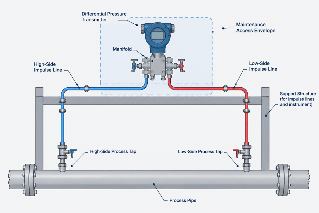
Plate removal and maintenance access
The assembly must be accessible after surrounding piping, insulation, platforms, cable trays, and structural steel are installed. Plate removal may require loosening the joint and using the hardware provided for flange separation or plate handling. The required procedure and space should be confirmed from the selected assembly documentation.
Review the model for tool access, bolt withdrawal, plate extraction, instrument valve operation, and safe technician approach. Also consider whether insulation or removable covers could block plate identification or joint hardware.
A maintenance envelope is especially useful where the meter is near a wall, rack column, platform edge, or another pipeline. Keep the envelope separate from hard-clash geometry so reviewers can distinguish an access concern from a physical interference.
Isometric and drawing information
A fabrication or installation drawing should communicate more than a generic flange callout. Depending on project procedures, useful information may include:
- Meter or instrument tag
- Flow arrow
- Orifice flange and plate identification
- High-side and low-side tap identification
- Tap clocking or orientation reference
- Verified assembly dimensions
- Upstream and downstream references
- Instrument hookup or detail reference
- Required field orientation notes
Avoid duplicating detailed plate bore or instrument calibration information when those values are controlled in another document. Instead, provide an unambiguous tag or cross-reference so fabrication and installation teams can locate the governing data.
Common CAD errors
- Using ordinary flange geometry: The model omits the plate, tap connections, or actual joint stack-up.
- Ignoring upstream and downstream sides: The assembly appears symmetrical even though its measurement connections are directional.
- Guessing tap clocking: Pressure connections conflict with bolts, structures, insulation, or instrument routing.
- Routing a disturbance too close: A fitting or valve enters a controlled meter-run region.
- Leaving no plate-removal space: The joint fits geometrically but cannot be serviced.
- Mixing document ownership: CAD attributes conflict with approved instrument or process data.
- Modeling impulse lines without coordination: High and low sides are crossed, unsupported, or routed in a way that prevents suitable venting or draining.
A practical review sequence
- Confirm the line number, service, size, material class, and flange requirements.
- Obtain the approved meter identification and measurement arrangement.
- Verify the assembly dimensions from the governing component data.
- Establish flow direction and upstream/downstream orientation.
- Place the flange pair, plate position, and pressure taps accurately.
- Apply verified straight-run or disturbance-control requirements.
- Coordinate tap clocking with bolts, impulse lines, and access.
- Check supports, pipe movement, insulation, and maintenance space.
- Compare the model, P&ID, instrument index, line list, and hookup details.
- Ensure isometrics and drawings preserve the critical orientation information.
The best CAD model is not necessarily the one with the most small hardware. It is the one that clearly preserves the functional relationships needed for procurement, fabrication, installation, and instrument commissioning. By treating the orifice flange pair as part of a complete measurement system, designers can identify layout problems before they become field modifications or unreliable readings.
Managing meter data through the CAD workflow
A meter run often develops through several design stages. Early routing may show only a tagged measurement location, while later model updates introduce verified flange geometry, tap orientation, instrument interfaces, supports, and access envelopes. Each update should retain the approved measurement intent rather than allowing temporary assumptions to become fabrication information.
Separate controlled data from layout aids
Useful model attributes can identify the meter tag, flow direction, upstream side, downstream side, tap designation, and source document. Temporary straight-run zones, maintenance envelopes, and instrument-routing studies should be clearly classified as reference geometry. This prevents non-fabricated objects from appearing as physical materials or creating misleading drawing output.
Coordinate model revisions across disciplines
A change to nearby piping can affect more than spatial clearance. Moving an elbow, valve, branch, support, platform, or transmitter may alter the accepted meter arrangement or make the assembly difficult to operate and maintain. Relevant changes should therefore be reviewed with process, instrumentation, piping, and structural participants before drawings are released.
- Process review: Confirm that the measurement location and flow direction remain valid.
- Instrumentation review: Confirm tap assignment, transmitter arrangement, and impulse-line interfaces.
- Piping review: Confirm component selection, joint geometry, routing, insulation, and access.
- Structural review: Confirm that supports and nearby steel do not obstruct the assembly or its maintenance path.
Use drawing output as a model-quality check
A model can appear correct in a shaded view while producing an ambiguous isometric. Review plotted output to verify that the plate location, flow arrow, tap identification, and meter tag remain readable. Where geometry alone cannot communicate direction or function, use controlled notes and attributes that agree with the governing documents.
Before issue, compare the piping model with the P&ID, line data, instrument information, hookup details, and approved component documentation. Any conflict should be resolved by the responsible discipline rather than hidden with drafting adjustments.
Frequently asked questions
Is an orifice flange pair the same as a meter run?
No. The flange pair holds the orifice plate and provides pressure-tap connections. The meter run is the broader measurement arrangement, which may include adjoining straight pipe, nearby fittings, flow-conditioning equipment, instrument connections, and supports.
Can ordinary flange geometry be used for an orifice flange assembly?
Generic geometry may be acceptable for an early conceptual representation, but it should not control fabrication or installation. Detailed CAD work should use verified assembly data and represent the plate location, taps, orientation, and actual joint arrangement.
Who determines the required upstream and downstream arrangement?
The requirement should come from approved process, instrumentation, or purchased-equipment documentation. A CAD designer should not infer it from a generic drafting convention.
Why must flow direction appear in the model and drawings?
Flow direction establishes the upstream and downstream sides and supports correct identification of the pressure connections. If that information is lost, a physically connected installation may still be functionally incorrect.
Should impulse tubing be modeled in detail?
The appropriate level of detail depends on the project workflow. Whether shown schematically or modeled physically, the routing should preserve high-side and low-side identity, approved venting or draining behavior, support needs, access, and instrument interfaces.
How should maintenance clearance be represented?
A separate reference envelope can show the area needed for plate handling, joint access, tools, and instrument operation. It should be identified as non-fabricated geometry and reviewed alongside insulation, structures, platforms, and adjacent piping.
What should happen when piping and instrument documents disagree?
The discrepancy should be referred to the responsible disciplines for resolution. Do not silently revise tags, tap assignments, flow direction, or controlled meter information only to make the drawings appear consistent.