Tag: piping drafting

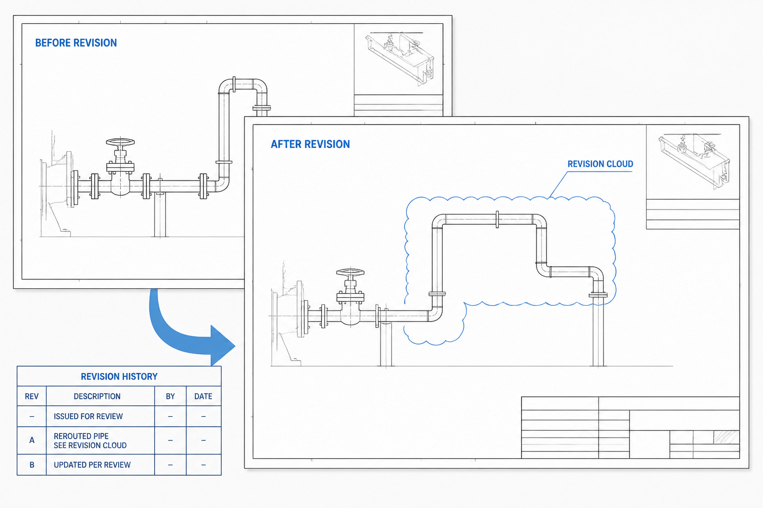
  • Piping CAD Revision Control: How to Mark, Track, and Verify Drawing Changes

    Piping CAD Revision Control: How to Mark, Track, and Verify Drawing Changes

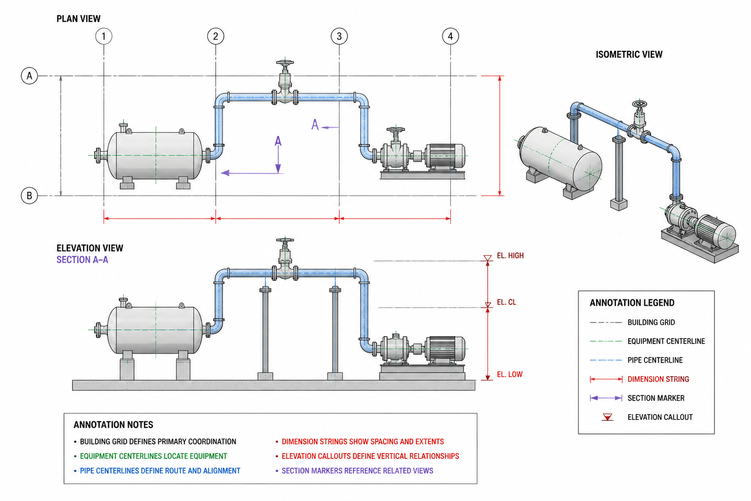
  • Piping Coordinate Dimensions in CAD: A Practical Guide to Clear, Verifiable Routing

    Piping Coordinate Dimensions in CAD: A Practical Guide to Clear, Verifiable Routing

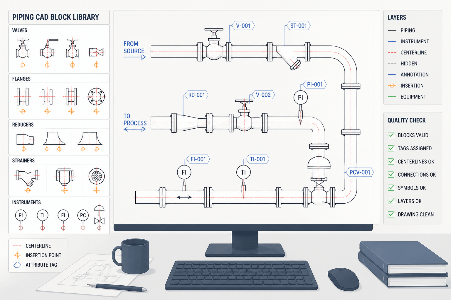
  • Piping CAD Blocks: How to Build, Use, and Check a Reliable Component Library

    Piping CAD Blocks: How to Build, Use, and Check a Reliable Component Library

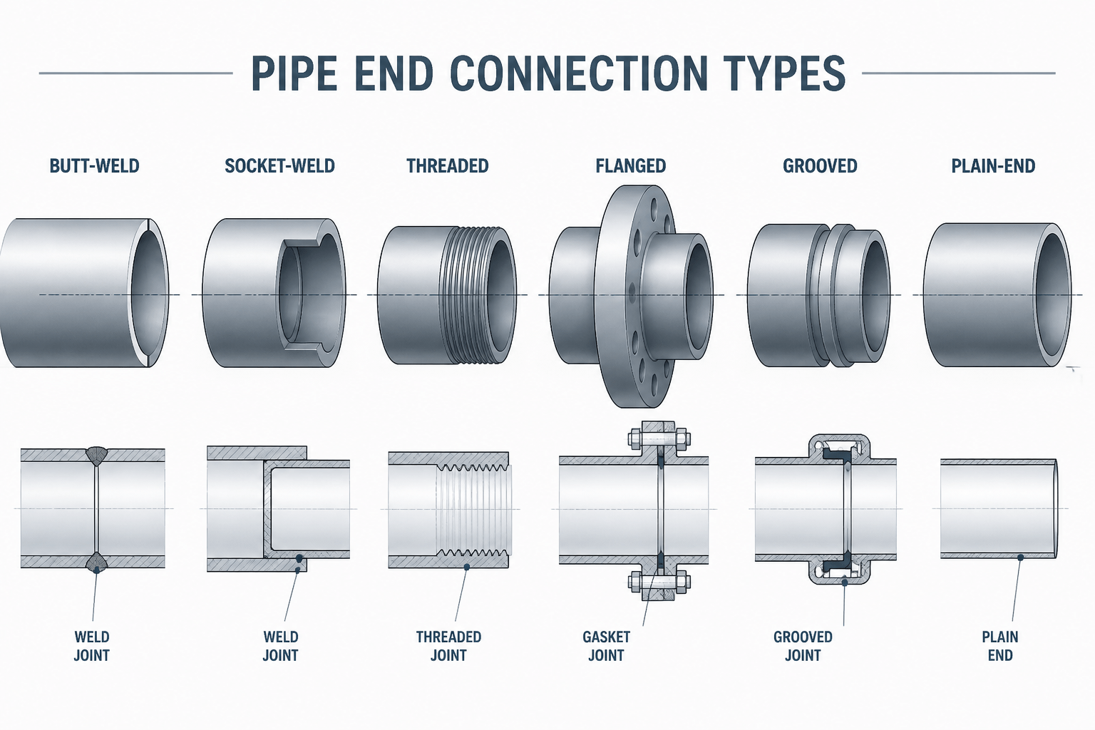
  • Pipe End Connection Types: How to Read and Detail Them in CAD

    Pipe End Connection Types: How to Read and Detail Them in CAD

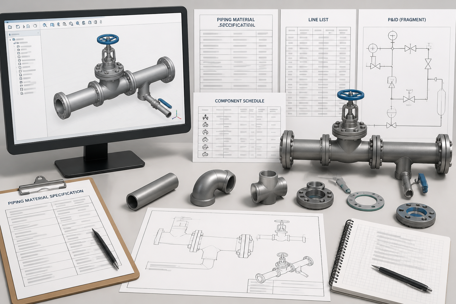
  • How to Read a Piping Material Specification Before Drafting in CAD

    How to Read a Piping Material Specification Before Drafting in CAD

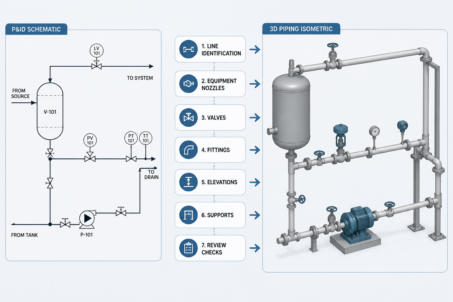
  • How to Turn P&ID Piping Information into a CAD Isometric Checklist

    How to Turn P&ID Piping Information into a CAD Isometric Checklist

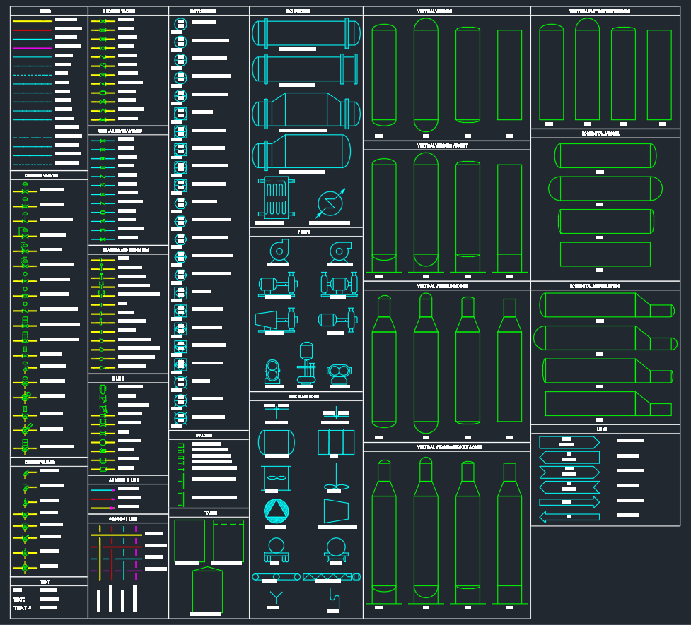
  • P&ID Symbols | DWG Library for Process & Instrumentation Diagrams

    P&ID Symbols | DWG Library for Process & Instrumentation Diagrams

  • Pressure Reducing Valve CAD Blocks (PRV) – DWG Symbols & Sizes

    Pressure Reducing Valve CAD Blocks (PRV) – DWG Symbols & Sizes

  • Globe Valve Butt-Weld End CAD Blocks (ARI) – DWG Sizes DN15–DN350

    Globe Valve Butt-Weld End CAD Blocks (ARI) – DWG Sizes DN15–DN350