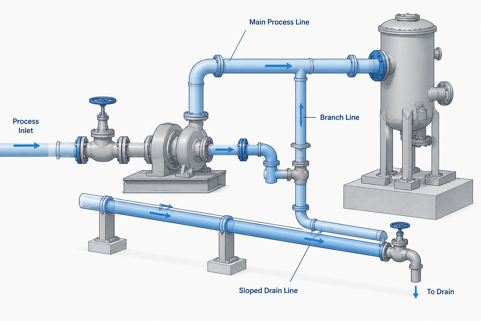
Piping flow direction arrows in CAD are small annotations that help reviewers trace a line through equipment, branches, fittings, and drawing breaks. Their value depends on more than visual placement: each arrow should reflect verified connectivity and a defined operating condition.
This guide explains how to choose the correct direction, place arrows clearly, coordinate them across drawing types, and review special cases such as branches, bypasses, drains, vents, and reversible lines.
Piping flow direction arrows are small graphic elements with a large coordination responsibility. They help readers understand how a line is intended to operate, but they can also create confusion when they are missing, duplicated, reversed, or applied to a line that does not have one simple flow direction.
In CAD deliverables, an arrow should support the information already carried by the P&ID, line list, equipment arrangement, and project drafting conventions. It should not be used to guess process behavior or replace a formal design review. The most reliable approach is to treat the arrow as a checked annotation linked to a known flow path.
What a piping flow arrow communicates
A flow arrow normally indicates the intended direction of fluid movement through a pipe segment or connected piping route. Depending on the drawing type, it may communicate one of several related ideas:
- Process flow: movement from an upstream source toward downstream equipment, piping, or a battery limit.
- Utility distribution: movement from a header toward users, or from a source toward a return system.
- Drainage direction: movement toward a low point, drain collection point, or disposal connection.
- Temporary or alternate operation: a route used during startup, flushing, bypassing, circulation, or another defined operating condition.
These meanings are not interchangeable. A line may be physically connected in CAD while its normal operating direction depends on a process condition, control strategy, or operating mode. When that distinction matters, the drawing should use the project’s approved notes, line data, or operating designations rather than relying on an unexplained arrow.
Where arrows belong in a CAD drawing
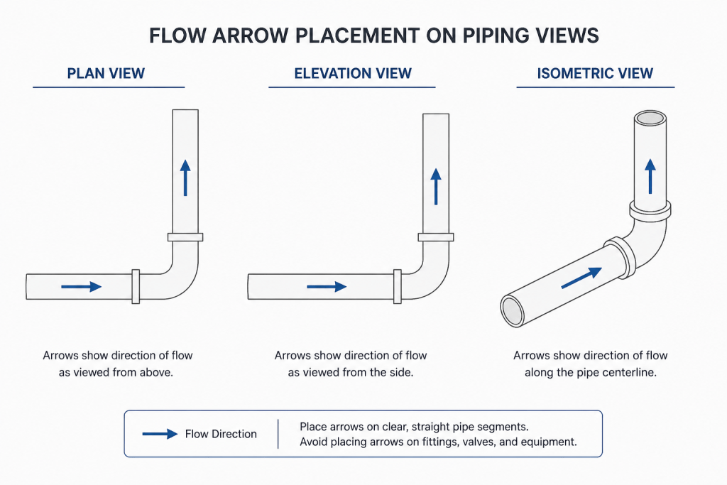
Place arrows where a reader can associate them with the correct pipe run without mistaking them for a valve symbol, instrument leader, dimension line, or weld annotation. Common locations include long straight pipe segments, approach runs to equipment, utility branches, and areas where the route changes direction or crosses another line.
On a plan or elevation, an arrow is most useful when the line direction is not immediately obvious from nearby equipment labels. On an isometric, place it on an unobstructed segment and orient it to follow the pipe axis. Avoid placing an arrow directly over a fitting, flange, support symbol, insulation break, or dense group of callouts.
Use enough arrows to maintain orientation across a large or segmented drawing, but avoid adding one to every short segment. Excessive repetition creates visual noise and makes it harder to identify the meaningful direction changes. A good placement pattern lets the reader follow the line from one arrow to the next without searching the entire sheet.
How to determine the correct direction before drafting
Do not infer direction solely from the left-to-right or bottom-to-top layout of a drawing. CAD space is arranged for clarity, not necessarily to represent process movement. Before placing an arrow, trace the line through its connected components and compare that path with the controlling project information.
1. Identify the operating case
Confirm whether the drawing represents normal operation, a utility service, a drain, a vent, a temporary connection, or another defined condition. A bypass or cross-connection may have a different direction from the main route, and a reversible system may require a note instead of a single directional arrow.
2. Trace from a known source to a known destination
Use equipment tags, line numbers, P&ID connectivity, nozzle designations, and battery-limit information to establish the intended route. Follow every branch that affects the interpretation. A line that appears to flow toward a vessel may actually be a vessel outlet, while a line that appears to leave a pump may be a suction route depending on the equipment arrangement.
3. Check inline components
Review valves, check valves, strainers, filters, meters, control devices, and other directional components. Their intended orientation can provide an important cross-check, but it should not override the approved process information. If the component orientation and proposed arrow disagree, stop and resolve the data conflict before issuing the drawing.
4. Check elevation and drainage intent
For sloped lines, the arrow may follow the intended drainage direction rather than the apparent horizontal route. A drawing should make both the slope and the flow interpretation understandable. If a line can drain in more than one operating condition, use the project’s designated notation or a clarifying note.
Flow arrows on different drawing types
| Drawing type | Primary purpose of the arrow | Important check |
|---|---|---|
| P&ID | Show process or utility movement between functional items | Match the approved process connectivity and operating intent |
| Plan view | Help the reader follow a routed line across the layout | Keep the arrow associated with the correct line where routes cross |
| Elevation or section | Clarify vertical movement, slope, and equipment connections | Compare direction with elevations, drains, vents, and nozzle roles |
| Isometric | Support line tracing and component identification | Place the arrow on a clear pipe segment and preserve readability |
| Spool or fabrication view | Provide orientation for assembly or review when required | Do not let the arrow substitute for spool weld, end, or connection data |
The same line may show arrows in several drawing types, but each view has a different reader need. A process drawing emphasizes functional direction, while an isometric emphasizes traceability through a physical route. Keep the meaning consistent, but adjust placement and density to suit the view.
Special cases that need careful treatment
Branch lines
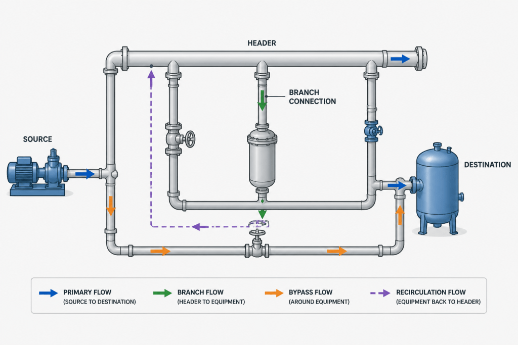
A branch arrow should describe the direction in that branch, not simply repeat the direction of the header. At a tee or other branch connection, verify whether the branch is supplying a user, receiving flow, draining a system, or serving as a possible alternate route.
Bidirectional or reversible lines
Some lines can operate in either direction. A single arrow may be misleading in this situation. Use the approved project convention, such as opposed arrows or an explanatory note, only when the operating basis supports that representation. Do not assume that physical connectivity means bidirectional service.
Recirculation and bypass routes
Recirculation lines can return flow toward an upstream vessel, pump suction, header, or other destination. Bypass lines may be inactive during normal operation but important during startup or maintenance. Their arrows should be coordinated with the operating description and valve lineup, not added as a visual guess.
Drains and vents
Drains commonly depend on gravity and low-point geometry, while vents often depend on high-point location and the intended release or collection point. Check the elevation view and line slope rather than placing arrows based only on the plan layout.
CAD implementation practices
Use a consistent arrow block or annotation style controlled by the project template. Keep the arrow visually distinct from dimension leaders and other symbols, and make sure it remains legible at the plotted scale. If the project uses layers for process annotations, place arrows on the appropriate annotation layer rather than embedding them unpredictably in equipment or pipe geometry.
For model-based workflows, store the direction as a property of the relevant line segment or logical connection when the software supports it. Then generate or review drawing arrows from that data. In a two-dimensional workflow, maintain a simple review field or checklist so that each major line has a confirmed direction source.
When a line is broken by a match line, continuation symbol, or drawing boundary, repeat the directional information where needed to preserve traceability. The continuation should not force the reader to infer direction from a remote sheet.
Flow arrow review checklist
- Is the arrow associated with the intended line and operating case?
- Does it agree with the approved P&ID or other controlling source?
- Does it follow the actual connected route through fittings and branches?
- Does it agree with directional components and equipment connection roles?
- Is drainage or venting direction consistent with the elevation and slope?
- Are reversible, temporary, bypass, and alternate routes clearly identified?
- Is the arrow readable at the issued plot scale?
- Is it separated from symbols, dimensions, leaders, and crossing lines?
- Are continuation sheets and drawing breaks still understandable?
Conclusion
A piping flow direction arrow is effective only when it is tied to verified connectivity and a defined operating intent. The drafting task is not merely to draw an arrow on a pipe; it is to make the route understandable without introducing a new assumption. Trace the line, confirm the operating case, check equipment and elevation relationships, and place the annotation where it improves reading. Used consistently, flow arrows make plans, elevations, isometrics, and related CAD documents easier to review and less likely to be misinterpreted.
Why flow-arrow coordination matters
A flow arrow is an interpretation aid, not an independent source of process information. It should reinforce the approved line data and drawing conventions already used by the project. If the arrow conflicts with a P&ID, equipment connection role, valve orientation, or drainage intent, the conflict should be resolved before the drawing is issued.
Separate physical routing from operating intent
A CAD route shows where a pipe is drawn and connected. It does not automatically establish how the system operates. A connected line may serve as a supply, return, suction, discharge, drain, vent, bypass, or temporary route depending on the operating case. Reviewers should therefore distinguish geometric continuity from functional direction.
Use arrows to support line tracing
The best arrow locations help a reader move through the drawing without interrupting symbols, dimensions, leaders, or component callouts. On complex sheets, consistent placement is more useful than dense repetition. When a route crosses a boundary or continues on another sheet, the annotation should preserve enough context for the reader to continue tracing it confidently.
Coordinate arrows with the drawing hierarchy
Different documents answer different questions. A P&ID emphasizes functional connectivity, a plan emphasizes horizontal routing, an elevation emphasizes vertical relationships and slope, and an isometric emphasizes physical traceability. The direction should remain consistent where the operating case is the same, while placement and annotation density should be adapted to the drawing type.
Resolve ambiguity instead of hiding it
Opposed flow possibilities, alternate operation, recirculation, and temporary service can make a single arrow unsuitable. In these situations, use the project-approved notation or an explanatory note after confirming the operating basis. Do not use an arrow to imply certainty when the source information remains unresolved.
Practical review questions
- What source establishes the operating direction?
- Does the arrow follow the logical route rather than the visual orientation of the sheet?
- Are branches, returns, bypasses, drains, and vents interpreted separately from the main route?
- Can the arrow be read clearly at the issued drawing scale?
- Could another symbol, line crossing, or callout make the arrow appear to belong to a different pipe?
- Does the annotation remain understandable across match lines, continuation symbols, and related views?
Frequently asked questions
Should every pipe segment have a flow arrow?
No. Arrows should be placed often enough to support line tracing, but excessive repetition can clutter the drawing. Use clear, unobstructed segments and repeat the information where a drawing break or complex route could otherwise cause confusion.
Can flow direction be determined from the CAD layout alone?
No. The left-to-right or bottom-to-top arrangement of a drawing is not reliable evidence of process direction. Confirm the route against the controlling process, line, equipment, and operating information.
How should arrows be handled on bidirectional lines?
A single arrow may create a false impression on a reversible line. Apply the approved project convention or explanatory note only after confirming that the line can operate in both directions under the relevant operating conditions.
Where should an arrow be placed on an isometric?
Place it on a clear pipe segment where it follows the pipe axis and remains separate from fittings, flanges, supports, insulation breaks, and dense callouts. The location should help the reader trace the physical route.
Do valve or check-valve symbols determine the flow arrow?
They provide a useful cross-check, especially when the component has a directional function, but they do not replace the approved process information. Any disagreement should be investigated before issue.
How should drains and vents be reviewed?
Review their elevation, slope, high-point or low-point role, and intended collection or release location. Plan-view appearance alone may not show the relevant direction.