Category: How To

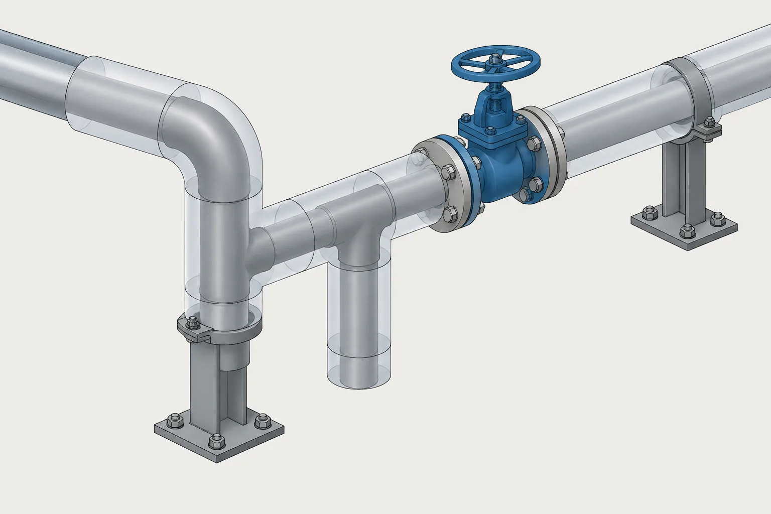
  • Pipe Insulation in CAD: Modeling the Outer Envelope, Thickness Changes, and Removable Covers

    Pipe Insulation in CAD: Modeling the Outer Envelope, Thickness Changes, and Removable Covers

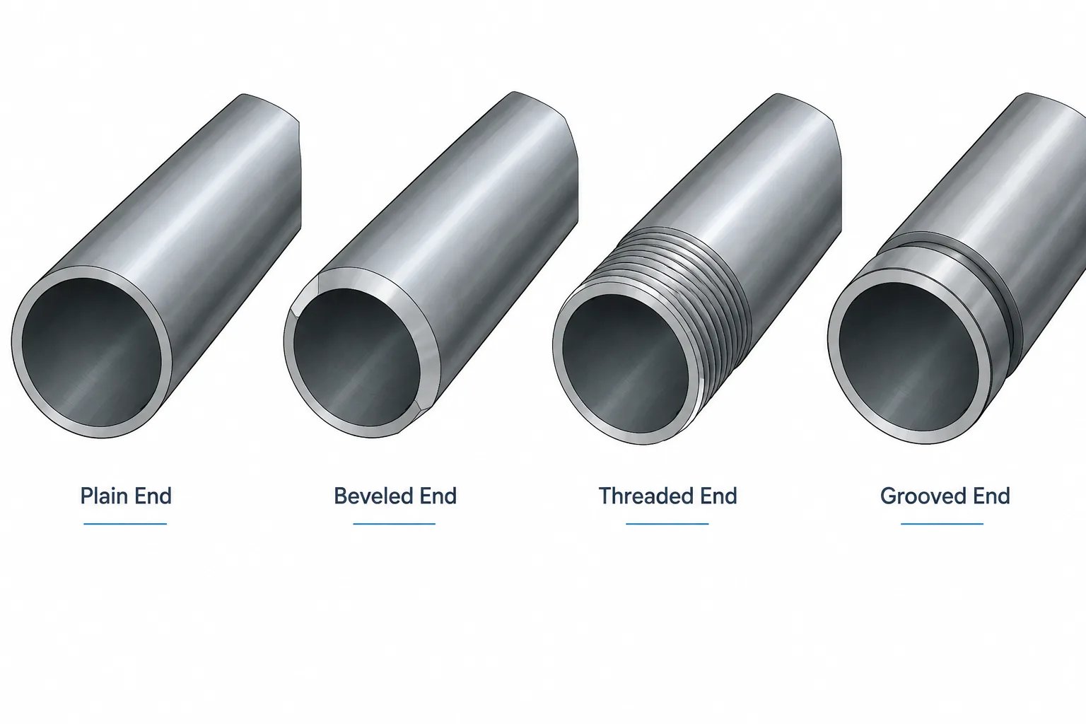
  • Pipe End Types in CAD and Piping Documentation: Plain, Beveled, Threaded, and Grooved Ends

    Pipe End Types in CAD and Piping Documentation: Plain, Beveled, Threaded, and Grooved Ends

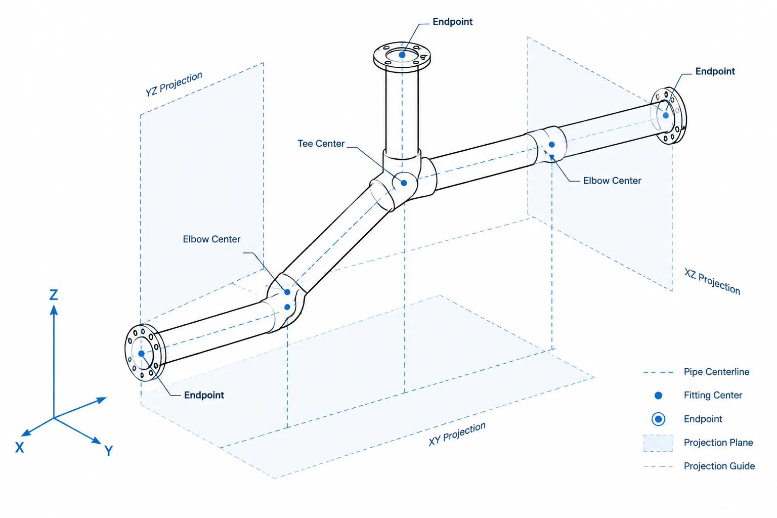
  • Skewed Pipe Runs on Isometric Drawings: True Length, Coordinates, and CAD Checks

    Skewed Pipe Runs on Isometric Drawings: True Length, Coordinates, and CAD Checks

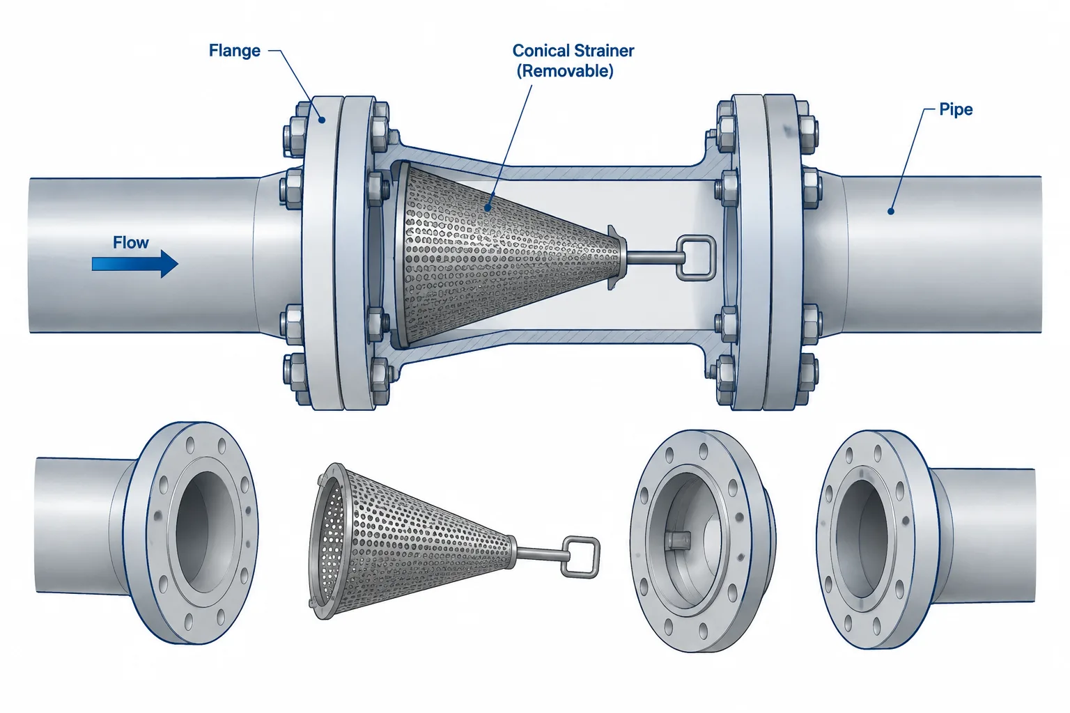
  • Temporary Strainers in Piping CAD: Placement, Orientation, and Removal Planning

    Temporary Strainers in Piping CAD: Placement, Orientation, and Removal Planning

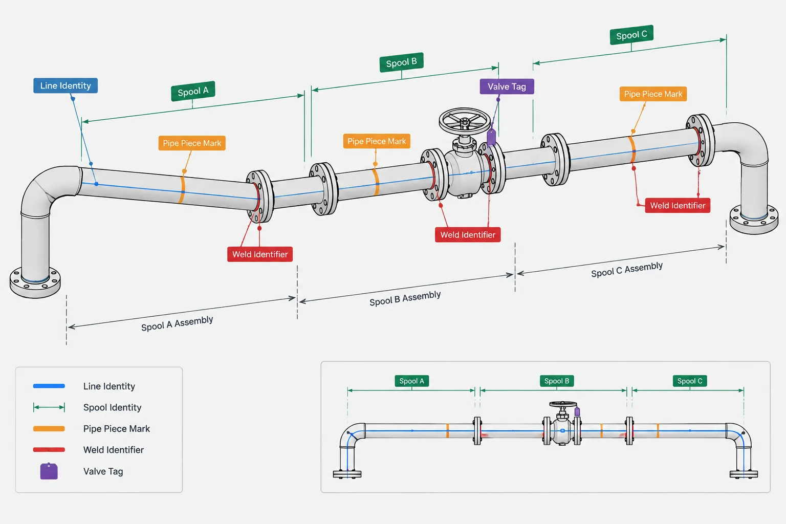
  • Pipe Spool Numbers, Piece Marks, and Line Numbers: What Each Identifier Controls

    Pipe Spool Numbers, Piece Marks, and Line Numbers: What Each Identifier Controls

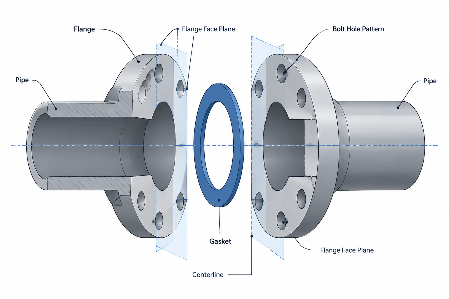
  • Flange Joint Alignment in Piping CAD: Faces, Bores, Bolt Holes, and Field Fit-Up

    Flange Joint Alignment in Piping CAD: Faces, Bores, Bolt Holes, and Field Fit-Up

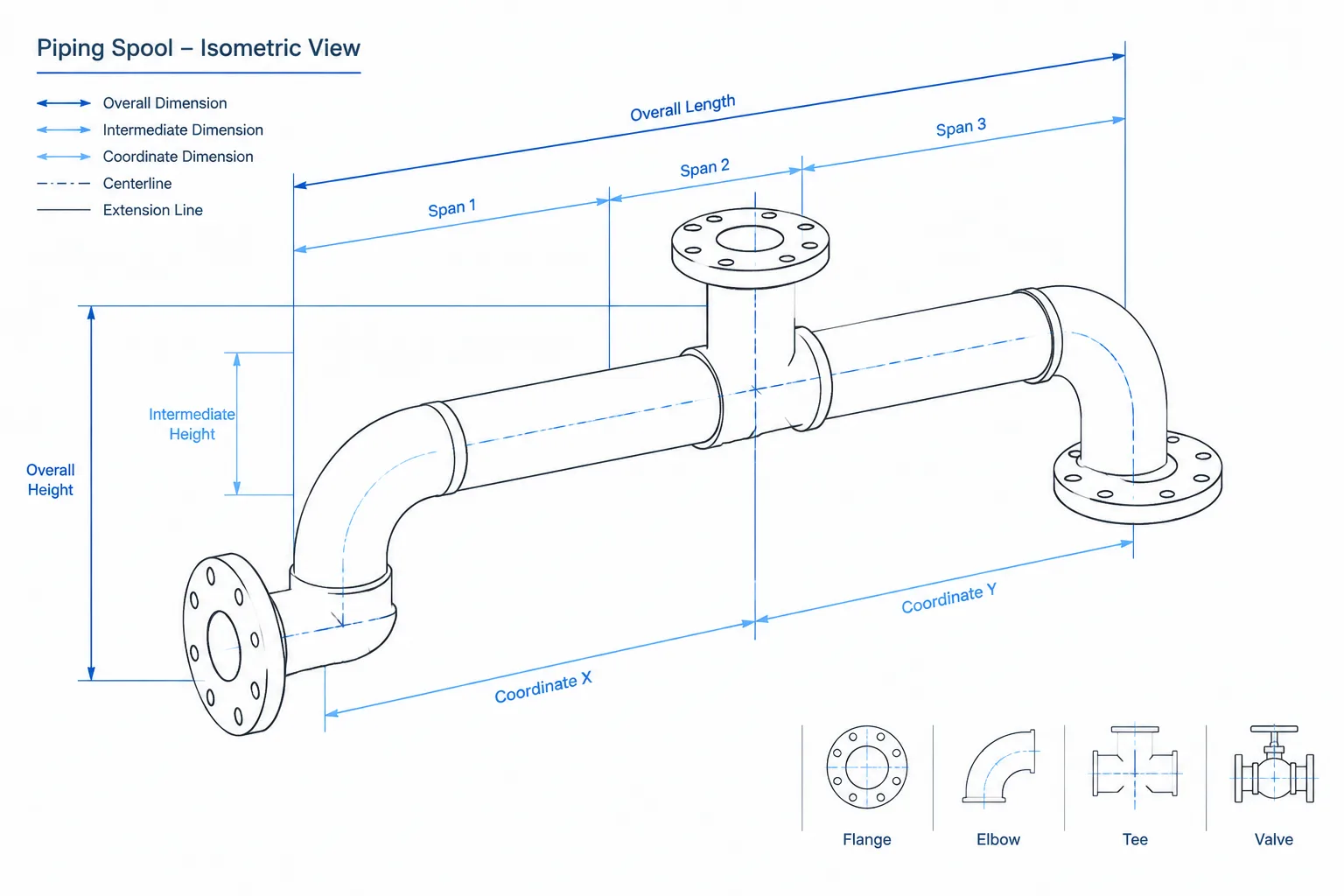
  • Piping Isometric Dimensioning: What to Control and What to Leave Derived

    Piping Isometric Dimensioning: What to Control and What to Leave Derived

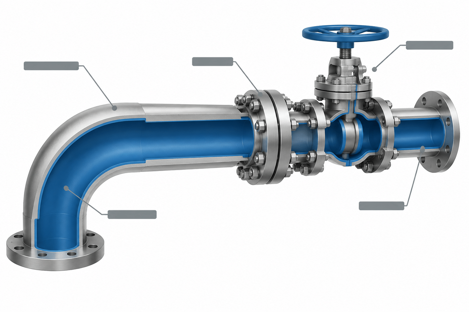
  • Lined Piping in CAD: How to Model, Specify, and Detail the Internal Barrier

    Lined Piping in CAD: How to Model, Specify, and Detail the Internal Barrier

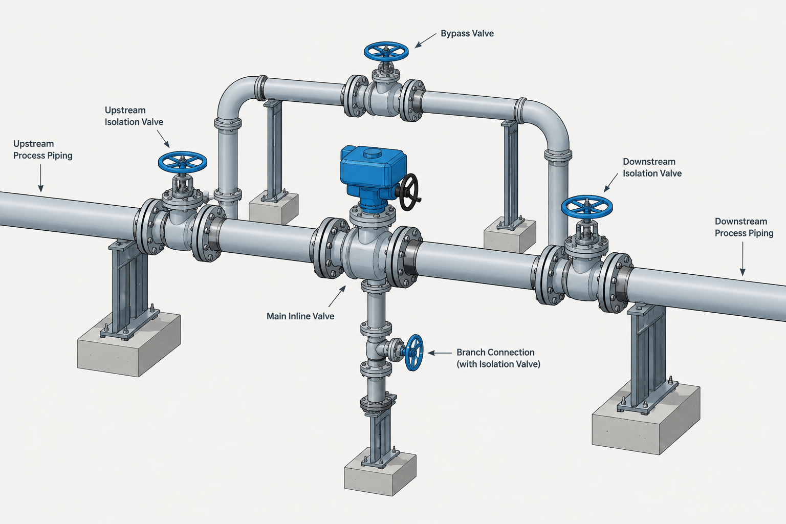
  • Valve Bypass Piping in CAD: Isolation, Operation, and Maintenance Layout

    Valve Bypass Piping in CAD: Isolation, Operation, and Maintenance Layout